DALI is a communication protocol that is used for the automation of lighting, which is not new at all. It is widely used especially in large buildings. We said it is not new … really it is.. DALI was invented by Philips in 1984, older than me. Folks who set standards can be found at: http://www.dali-ag.org
How does DALI Protocol work?
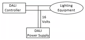
A simple DALI network consists of at least one controller, at least one DALI-compliant lighting equipment and at least one DALI power supply.
Control equipment; All lighting equipment in the DALI network can be controlled individually, in groups, or in a so-called “broadcast”. You can give commands like turning off, turning on, dimming the light. While changing all these values, it can receive power level values of these illuminations by the commands it sends to the network and if there is a fault in the lamps. Control equipment may be a computer software. Wall switches and sensors can also be classified as controlling equipment. For example, depending on the intensity of the light falling on the light sensor, the sensor device can directly interfere with the DALI network to which it is connected and control a configured lighting device or a group.
DALI devices are also configured via DALI line. In addition to the lighting commands; addressing, network integration, and device scanning functions are performed with the configuration commands defined in the protocol.
Addressing in DALI Protocol
In DALI network, each lighting device has a short address between 0 and 63. So it can control up to 64 devices. The answer to the question of what to do if there is more; is more controller ..
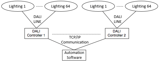
In addition to 64 device addresses, up to 16 device groups can be created. Device groups are used when more than one lighting is in the same room or part of the building/area.
One of the advantages of grouping is timing. We’ll go into details, but it takes 42 milliseconds to send each command. Basic math, it will take 30 * 42 milliseconds = 1.2 seconds to send 30 commands one by one in an environment with 30 lightning equipments.
Data Transmission in DALI
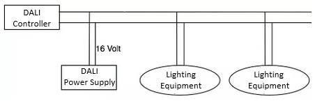
DALI Communication between the controller and DALI lighting equipment is provided by a single pair cable. There is even no polarization constraint. So you don’t have to worry about finding the “+” of the cable. Unlike most communication protocols, separate power supply equipment supplies the communication voltage on the line, not the devices. Devices only do the switching.
The DALI power supply should generate a potential difference between 16 and 22.5 Volts on the line. Values below 16 volts should be understood to indicate a leak or a different problem on the communication line. If you have a 22.5 Volt power supply, you may lose up to 2 volts which is 20.5 Volts.
Since DALI devices do not supply the line, they short-circuit the DALI line to increase the voltage level in the line to “0”. According to DALI standards, the power supply must provide a maximum current of 250mA. The purpose of this low current limitation is; When DALI equipment switches the line by short circuit, it does not draw excessive current on it and does not damage its own equipment.
DALI Cable Specifications
All lighting equipment communicates on the same line. The length of the line must not exceed 300 meters. Cable thicknesses according to line length are given in the table below:
| Line Lenght | Line Thickness |
| 0-100 meters | 0.5 mm2 |
| 100-150 meters | 0.75 mm2 |
| 150-300 meters | 1.5 mm2 |
The power supply must provide a maximum current of 250 mA as specified. Theoretically, each DALI device is designed to draw 2mA current. The cable used for the line must be insulated at 600V.
Even though the line is a little different from the asynchronous communication standards you know, as a result, 1s 0s fly over the cable. So the logic levels are important. The logic value table used in DALI is given below:
| Voltage Range | Logic Value |
| 0±4.5 V | 0 |
| 16±6.5 V | 1 |
Logic values are important, but the other important point is that the data is transmitted by “manchester code” method. So; We send 0 and 1 to send 1, and 1 and 0 to send 0.
‘You can read my article about Manchester Code if you like.‘
DALI Protocol Line Coding
Manchester Code, also known as phase code; is often used in asynchronous communication models without a separate clock line.
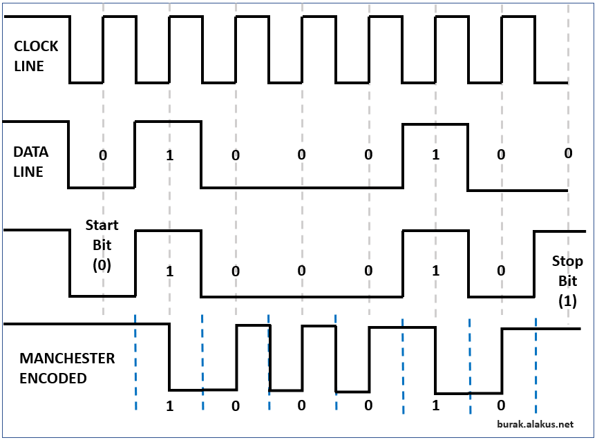
In the signaling flow, you can see the manchester encoded signal above. When you send this signal without an additional clock line, as the following manchester is not coded, the receiving device may make an error about how many “1”s and “0”s are there in this 8-bit frame. In this case, the synchronization is disrupted in communication and all data after the point at which the synchronization is disrupted is transmitted incorrectly. However, as seen above, the manchester encoded signal can have the same type of data for a maximum of 2 clocks period. The phase difference in each transmitted nible secures the synchronization.
DALI Data Frame Structure
DALI Data Frame Specifications
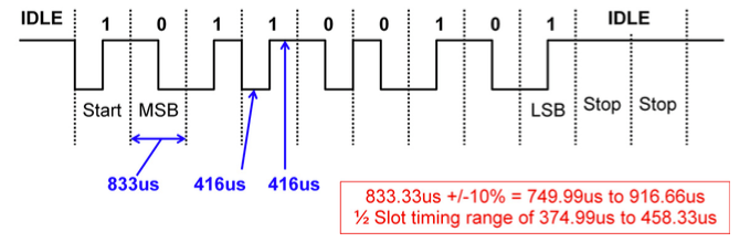
- When there is no data transmission on the DALI line, line logic is 1 (idle) (since the power supply is supplying the line permanently).
- Each DALI frame; starts with 1 start bit, and ends with IDLE for 2 bit time.
- Each bit duration is 833uS.
- By protocol definition; it has a tolerance of up to + – 10% deviation during the 833uS bit time.
- While transmitting data, the Most Significant bit is transmitted first.
- To achieve a bit duration of 833uS, your manchester coding algorithm must use a 416uS clock cycle.
- The DALI protocol does not have any mechanism to prevent collission. So; Before sending data, no checks done to see if another device is sending data at that time. In DALI, devices do not continuously keep alive keep alive mesaj messages. Therefore, there is no line use when idle. Since the line load is very low, there is a low probability of collision to be occurred.
- Data transmission is 1200 bits per second.
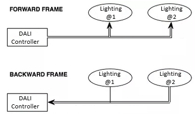
There are 2 types of data frame in DALI Protocol:
- Forward Frame; controller sends the data frame from the device to the lighting equipment (dali ballast).
- Backward Frame; is the response from the lighting equipment to the controller.
In the following message example, the controller sends a forward frame to ask for the brightness level of the lighting at address 2. This message actually goes to all the devices on the line. But the answer comes from the equipment at address 2 as a backward frame.
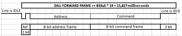
DALI Forward Frame Structure
DALI Forward Frame is from the controller to the lighting device (DALI Ballast). The 1-bit frame start bit (SoF) is constant “logic 1”. This is followed by an 8-bit address byte, an 8-bit command byte (payload), and an idle time with 2-bit clock duration.
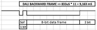
DALI Backward Frame Structure
DALI Backward Frame is from the lighting equipment (DALI Ballast) to the controller. The 1-bit frame start bit (SoF) is constant “logic 1”. This is followed by an 8-bit data byte and an idle time with 2-bit clock duration.
Conclusion
Although KNX is more popular right now, DALI has a simpler structure. This decreases the hardware design costs. If you are going to develop a product that will work KNX yourself, license fees and certifications are more challenging than DALI. The simplicity of DALI protocol means less system resources for the devices you design. You can even go with Microchip’s low-segment microcontrollers. DALI, KNX or X10 .. all can be used in one solution based on customer requirements. Hybrid systems is my favourite and they are very open for expansion in both ways.
Leave a Reply